|
|
||
|---|---|---|
| .. | ||
| glue.asm | ||
| Makefile | ||
| ps2ctl.asm | ||
| README.md | ||
| schema-595.png | ||
| schema-ps2.png | ||
| schema-t45.png | ||
| schema-z80.png | ||
Interfacing a PS/2 keyboard
Serial connection through ACIA is nice, but you are probably plugging a modern computer on the other side of that ACIA, right? Let's go a step further away from those machines and drive a PS/2 keyboard directly!
Goal
Have a PS/2 keyboard drive the stdio input of the Collapse OS shell instead of the ACIA.
Gathering parts
- A RC2014 Classic that could install the base recipe
- A PS/2 keyboard. A USB keyboard + PS/2 adapter should work, but I haven't tried it yet.
- A PS/2 female connector. Not so readily available, at least not on digikey. I de-soldered mine from an old motherboard I had laying around.
- ATtiny85/45/25 (main MCU for the device)
- 74xx595 (shift register)
- 40106 inverter gates
- Diodes for
A*,IORQ,RO. - Proto board, RC2014 header pins, wires, IC sockets, etc.
- AVRA
Building the PS/2 interface
Let's start with the PS/2 connector, which has two pins:
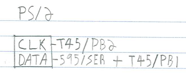
Both are connected to the ATtiny45, CLK being on PB2 to have INT0 on it.
The DATA line is multi-use. That is, PB1 is connected both to the PS/2 data
line and to the 595's SER. This saves us a precious pin.
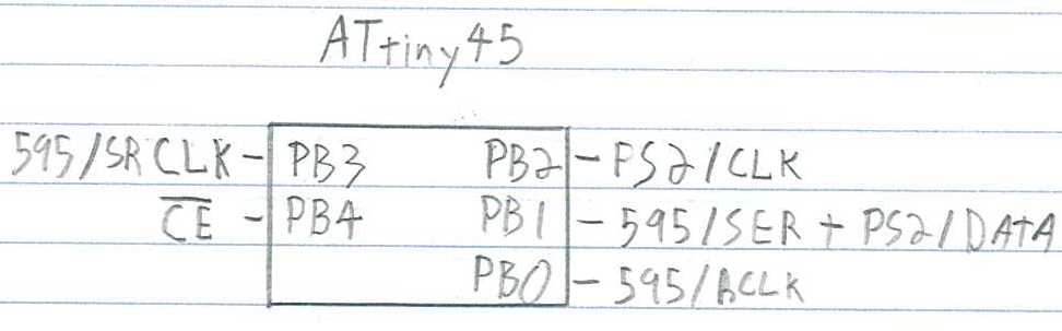
The ATtiny 45 hooks everything together. CE comes from the z80 bus, see below.
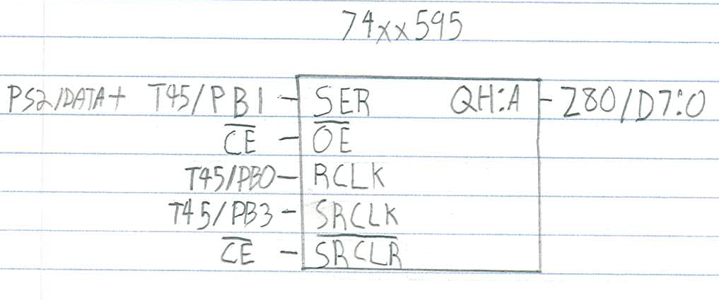
This allows us to supply the z80 bus with data within its 375ns limits. SRCLR
is hooked to the CE line so that whenever a byte is read, the 595 is zeroed
out as fast as possible so that the z80 doesn't read "false doubles".
The 595, to have its SRCLR becoming effective, needs a RCLK trigger, which
doesn't happen immediately. It's the ATtiny45, in its PCINT interrupt, that
takes care of doing that trigger (as fast as possible).
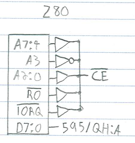
Our device is read only, on one port. That makes the "Chip Enable" (CE)
selection rather simple. In my design, I chose the IO port 8, so I inverted
A3. I chose a 40106 inverter to do that, do as you please for your own design.
I wanted to hook CE to a flip flop so that the MCU could relax a bit more
w.r.t. reacting to its PB4 pin changes, but I didn't have NAND gates that are
fast enough in stock, so I went with this design. But otherwise, I would
probably have gone the flip-flop way. Seems more solid.
Using the PS/2 interface
After having built and flashed the glue.asm supplied with this recipe, you end
up with a shell driven by the PS/2 keyboard (but it still outputs to ACIA).
There are still a few glitches, especially at initialization or at connect and disconnect, but it otherwise works rather well!